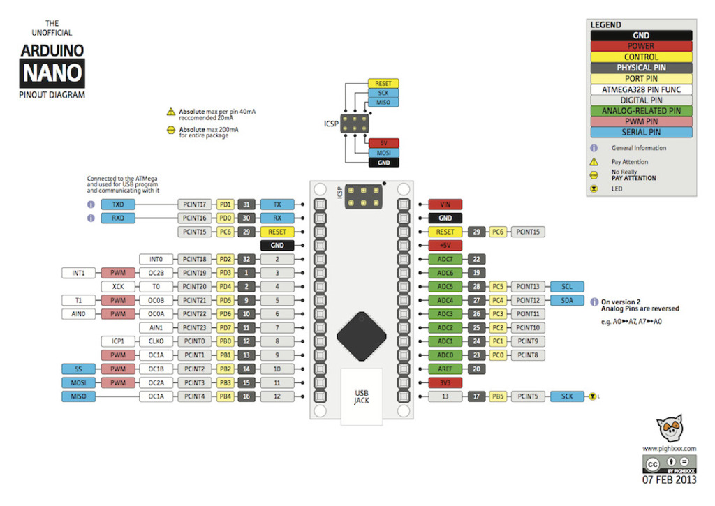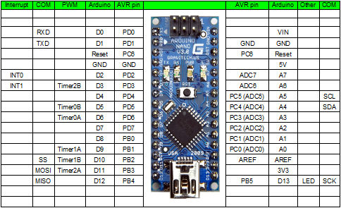
The pins for A0 to A7 are contiguous in the Arduino’s pin mappings – they map onto (internal) pins 14-21. Power supply In contrast, Arduino Uno has a DC power jack and a regular USB cable, while Arduino Nano uses a mini-B USB port hence can get power from the regular mini-B USB connection. The two extra pins on the Arduino Nano are for ADC functions. The Arduino does not have a built-in digital-to-analog converter (DAC), but it can pulse-width modulate (PWM). Pins -In contrast, Arduino Nano has 32 pins, while Arduino UNO has 30 pins. Out of these 22 pins, 14 are specific digital pins, 8 are analog pins and 11 can be used for PWM output. Arduino Nano 33 IoT Pinout: The Pinout of Arduino Nano 33 IoT shows that there are a total of 22 digital I/O pins on the board.

These analog pins are labeled A0 to A5 (whereas digital pins are labeled 0 to. It has one parameter which is the pin number. The board has an inbuilt orange LED connected to the digital pin 13. Each pin can provide or receive a maximum of 40 mA and has an internal pull-up resistor (disconnected by default) of 20-50 kOhms. There are several entries in this file that determine the mapping of Arduino pin labels to MCU ports and pins. The upper range can be changed using the AREF pin and analogReference() function. Each of the 20 digital i/o pins on the Arduino Leonardo can be used as an input or output, using pinMode (), digitalWrite (), and digitalRead () functions.
#ARDUINO NANO PINOUT NUMBERS SERIAL#
To allow the Arduino environment to support the extra analog inputs, there are a few lists and structures in the Arduino “pins” definition file for the Nano Every (the same place that we tweaked to add serial ports last time). Espressif produced a limited number of programmer / debugger boards.

Note that AIN6 (PD6) is not connected and that AIN7 (PD7) is used for AREF. The Arduino Uno pinout guide includes information you need about the different pins. Pins D4, D13 and A5 on the Nano are reprogrammed to accept hardware interrupts.Link to code. Reading the data sheet, we can see that the 16 analog inputs are mapped as follows (I’ve included the Arduino pin numbers for reference): The common baseline I/O and power pin layout for the Arduino consists of 14 discrete digital I/O pins, an analog reference, 3 ground pins, 6 analog input pins. But the ATmega4809 actually has 18 analog inputs, and the additional ones can be found as extra functions on some of the other pins.

This means that it supports 8 analog inputs, labelled A0 to A7, all along one side of the board.
#ARDUINO NANO PINOUT NUMBERS HOW TO#
The next part in my series on the Arduino Nano Every, looks at how to access the additional 6 analog inputs that can be found scattered around the digital IO pins.Īs I mentioned in my introductory article, the Arduino Nano Every works hard to be “pin compatible” with the original Arduino Nano.


 0 kommentar(er)
